CNC Camera
PAGE STILL UNDER CONSTRUCTION. PICS TO BE ADDED SOON.
Many ask about the camera on my CNC router so here's a quick rundown on what I'm using plus some options. The camera is a Dino-lite AM4023CT, using an additional Tamron 23FM25L lens with a 5 mm spacer. The settings I use will yield a magnification of 38.9X and a working distance of about 3". I find this to be ideal for my machine, based on the amount of Z travel I have & the clearance I need between the camera & assorted fixturing.
One person who inquired was kind enough to provide a more detailed description of the components, sources and links that will make your life easier. Well...regarding cnc cameras, that is. I've pasted his info below:
------------------------------------------------------------
Implementing
a High-Quality Digital Camera/Microscope for a CNC System
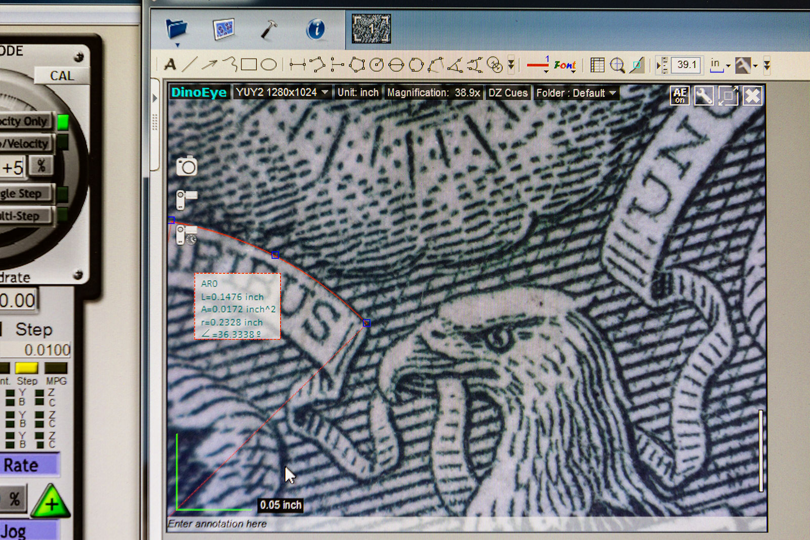
This shot of a dollar bill shows how you can pick 3 points on an arc (the top of the "pluribus" ribbon) to determine the exact radius of that arc. Note the detailed specifications in the box.
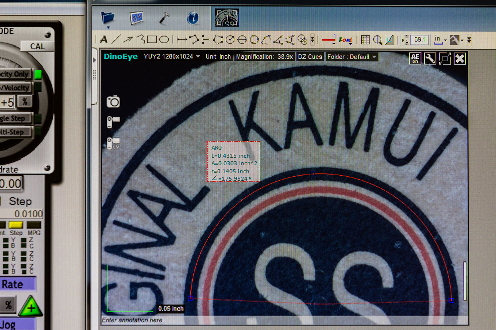
This example shows how easy it is to determine the diameter of the black circle on this Kamui tip.
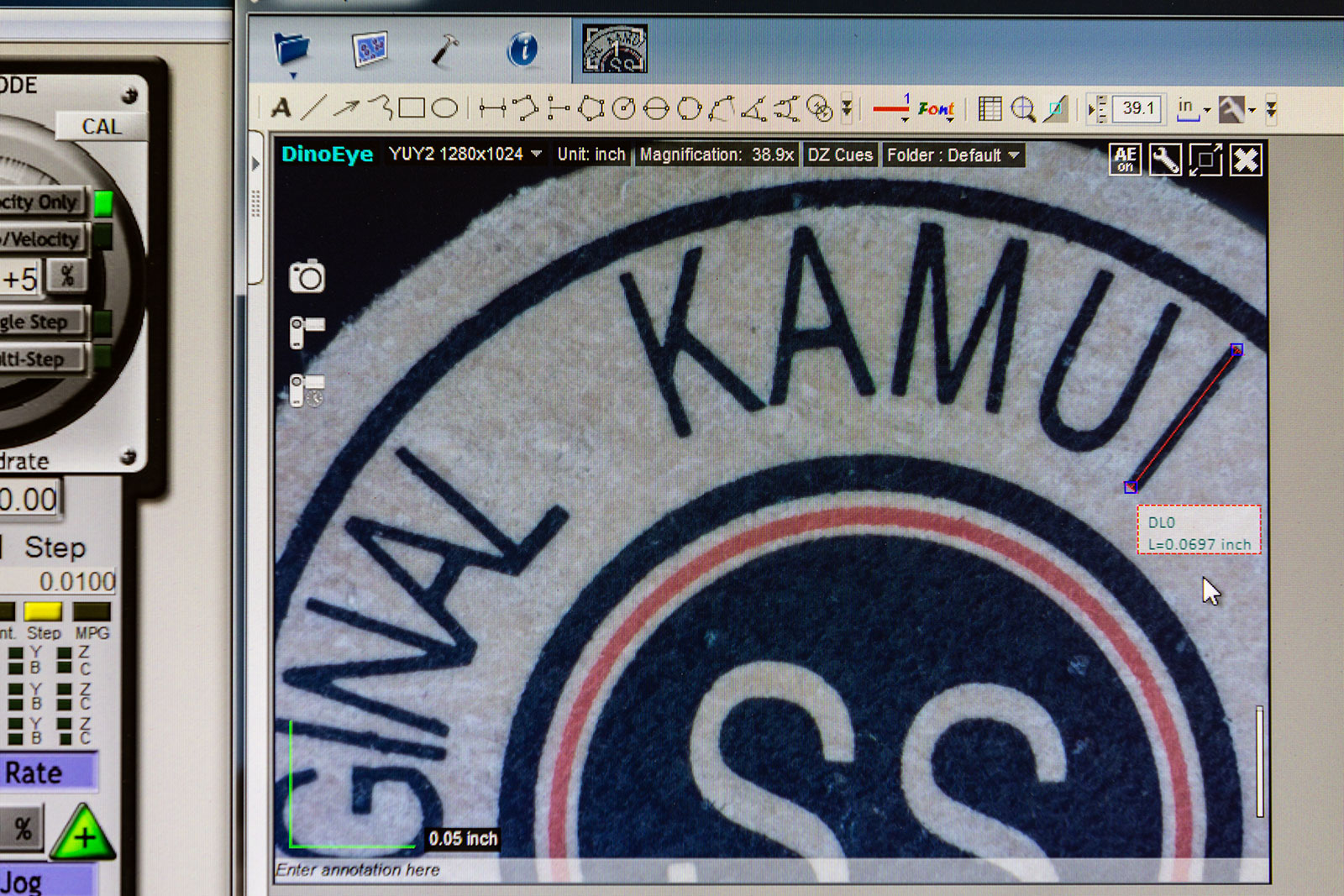
And here, we can easily determine the length of the letter "I" in Kamui.
---------------------------------------------------------------------
Also...
---------------------------------------------------------------------
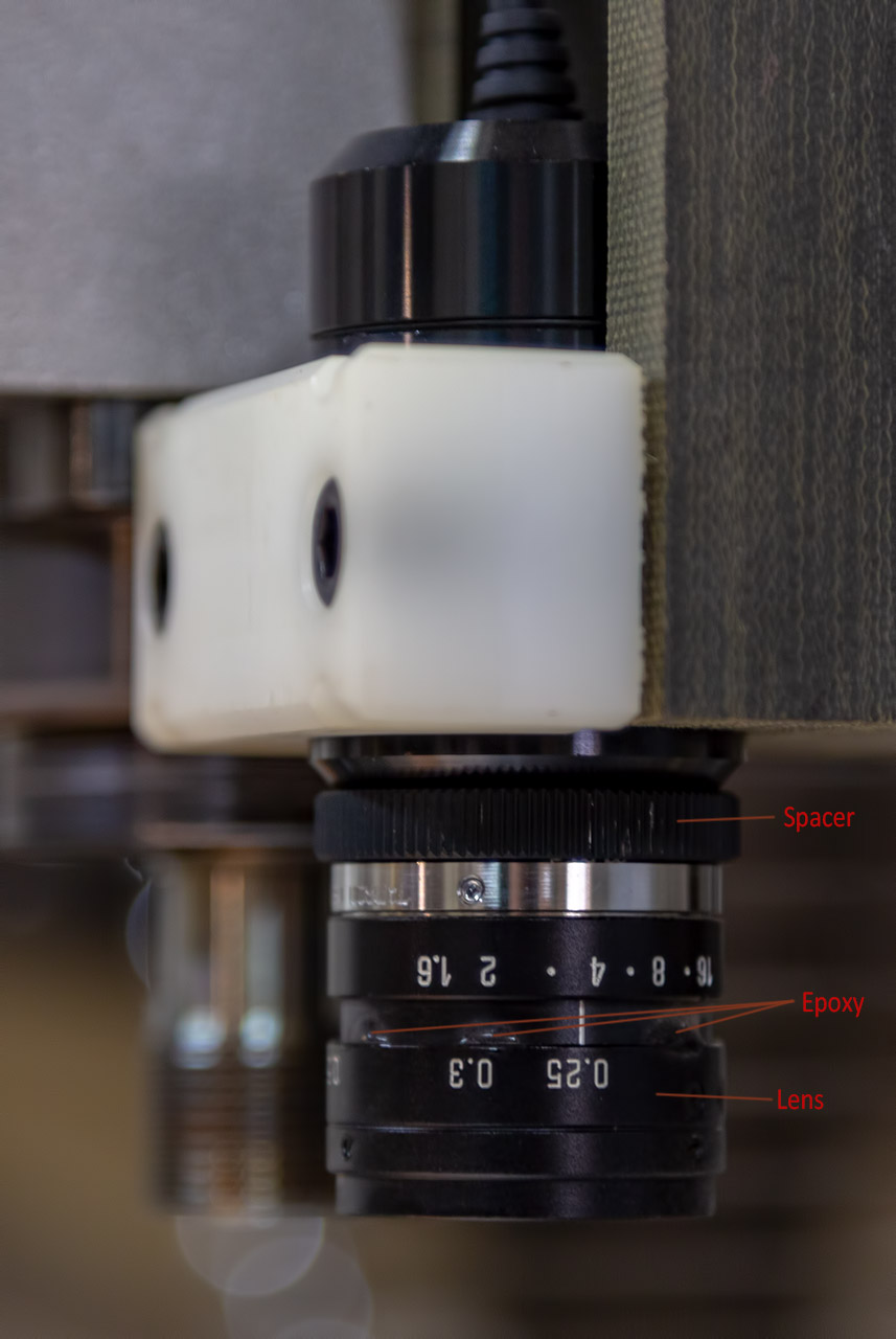
The package is assembled from three basic components:
A microscope eyepiece: Dino-lite AM4023CT, approx. $330.
A spacer: C mount to C mount spacer, approx. $15 or so
A CCTV lens: Tamron 23FMxxL, approx. $25+ on eBay (xx=focal length...see below)
Update: Dino-Lite now offers a holster for the camera. This will help with your mounting issues. You can see it HERE. Thanks, Phil!
The cost of the lens and length of the spacer will depend on which lens you select. The lens is designed to work with a “2/3” digital system, a sensor chip of 8.8 mm x 6.6 mm, - about “2/3” the size of a standard 35 mm digital camera sensor chip. This size is common in Closed Circuit TV systems and there are certainly lenses other than Tamron which would work and perhaps save a buck or two.
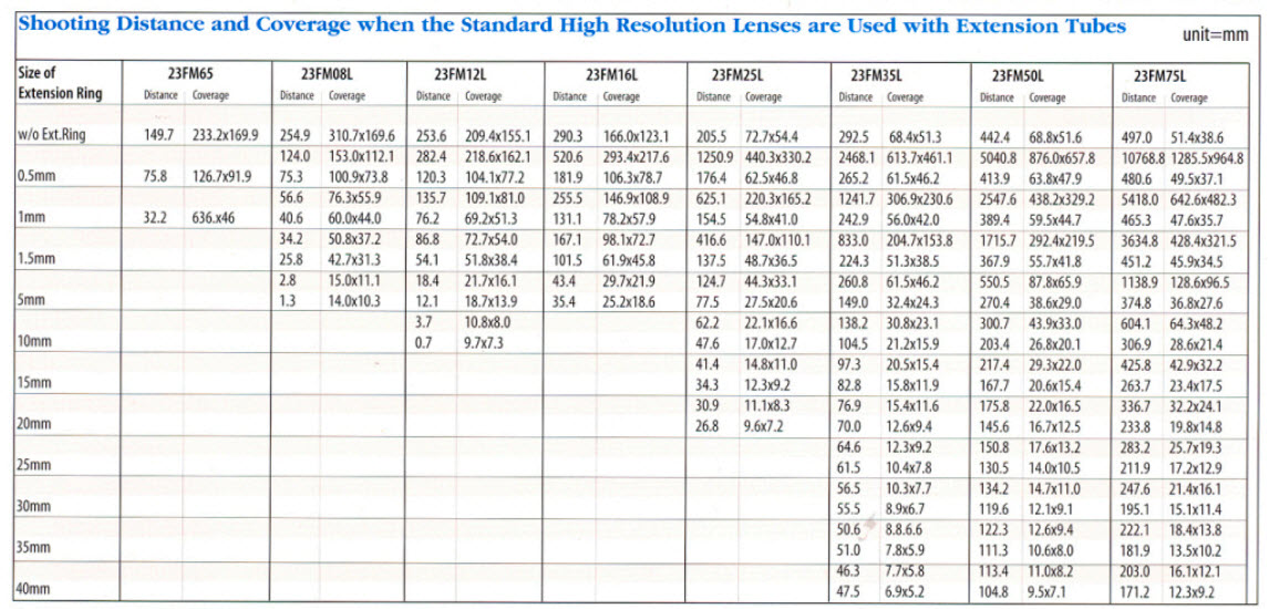
Both the 23FM25L with a 5 mm spacer and a 23FM35L with a 10 mm spacer are known to work, with the 35 mm option providing somewhat higher magnification. There seem to be more 35 mm Tamrons available on eBay than 25 mm at the moment, and at slightly lower cost. The chart below from Tamron gives the specifications for the lens and spacer combination. For instance, the 25 mm focal length with a 5 mm spacer shows a focus range of 77.5- 125.7 mm and a field of view range from 27.5 x 20.6 mm to 44.3 x 33.1 mm. You could also, for instance, use a 23FM50L and a 40 mm spacer – this combo would give a similar focus range, and a more extreme magnification. The size of the field of view gives you a relative comparison for the magnification relationship between focal length and magnification. The smaller the FOV, the higher would be the magnification.
The lowest numerical f stop gives a wide open aperture and hence, the brightest image. A higher f stop will often give a sharper image as the "sweet spot" for most lenses is in the f 4. - f 6. range. Some Tamron lenses have screws which you can tighten down to lock both the f stop ring, and the focal distance ring to keep them from moving once you find a combination which you like. The lens I used did not have lock screws so I applied a few spots of epoxy to prevent the lens settings from changing.
This table of lens combinations/options is available along with LOTS more technical detail here: LINK
----------------------------------------------------------------------------------------------------------
Changing the Button Scripts
I'll assume you know how to modify your button scripts but I'll
touch briefly on the process in Mach3: From the MDI screen, click
"Operator", then "Edit button script". You will notice several buttons
flashing. Choose which pair
you intend to modify and click the one on the left.
A window showing the current script will appear and this is the
script you will be changing.
The details of the script will vary depending on how & where you've
mounted your camera. The
numbers shown below are random numbers chosen to make the process
clear.
G91
An incremental move from your current position
G00
Rapid mode
X-2.375 Distance in X the spindle moves to position the camera
Y-.125 Distance in Y the spindle moves to position the camera
G90
Reverts to absolute mode
Close the window and click "yes" to save the changes.
You've successfully edited the button script.
Now you have to repeat the process for the button on the right.
This time, you will use the same script but
you must reverse the X and Y moves by removing the (-) negative sign
from both X and Y.
Now you have to change the button bitmaps.
Find the Mach3 folder on your computer, then the Bitmaps folder,
then the MillBitmaps folder.
Find the bitmaps that must be changed & note their names since the new
bitmaps you create must retain the same name and size as the original
buttons. Design your new
buttons in Paint or the graphics program of your choice, save them with
the correct names and install them in the same folder.
The next time you open Mach3, your buttons should be in place &
working properly.